Promoting CNC machine processing precision is a common goal for many bosses. It is not just about achieving higher quality products; it’s also about gaining a competitive advantage, meeting industry standards, reducing costs, and ensuring customer satisfaction. These factors contribute to the overall success and sustainability of a manufacturing business.
Currently commonly used methods include:
- Machine Calibration
- Spindle Accuracy
- Coolant and Lubrication
- Machine Rigidity
- Workpiece Fixturing
- Material Selection
- Programming Techniques
- Quality Control and Inspection
- Operator Training
- Environmental Control
These offer to improve the accuracy of machine tools is summarized in two basic methods: error prevention method and error compensation method. The error prevention method attempts to eliminate or reduce possible sources of error through design and manufacturing.
Error prevention method is the use of “hard technology”, it can reduce the original error, but by improving the accuracy of machine tool manufacturing and installation to meet the accuracy of the machine tool has great limitations, the economic cost is often very expensive, especially the need for more sophisticated machine tools as the production of machine tool workhorses.
Error compensation refers to artificially create a new error to offset or greatly weaken the original error of the current problem, through analysis, statistics, generalization and mastery of the characteristics and laws of the original error, the establishment of mathematical models of error, as far as possible to make the man-made error and the original error are equal to the value of the two, the direction of the opposite direction, so as to reduce the machining error and improve the dimensional accuracy of the parts. Error compensation is a “soft technology”, the cost of investment and improve the accuracy of the machine itself or the purchase of new high-precision machine tools compared to the price is much lower.
Error compensation technology is a significant economic value and very effective means of improving machine tool accuracy.
At present, the positioning error of CNC machine tools to compensate for the main methods are based on the measurement of the error data obtained by the CNC program modification, in the open CNC system can be used as a post-processing parameters for processing.
There is also a method is the most commonly used method is to use the CNC system has the error compensation function, the measured error data in the form of a table into the CNC system to compensate for the pitch error and backlash error and other errors, these are mainly for the geometric error class of more stable error.
Therefore, the biggest disadvantage of these compensation methods is that, as the machine tool in use, with the changes in the temperature field of the machine tool, machine tool positioning error and spindle drift will change with the changes in temperature, if the temperature changes caused by the error is too large, it will affect the machining accuracy of the workpiece to a large extent.
In order to overcome the existing machine tool CNC system can not be based on the temperature field of the machine tool for real-time error compensation or real-time compensation, but is not very perfect such as SIEMENS 840D can only compensate for linear positioning error of the movement axis of the temperature change, or the design of the implementation of the compensation device is more complex and difficult to apply the shortcomings of the practical application, there is now a machine tool based on the origin of the external coordinate system offset, according to temperature and position parameters of the CNC machine tool can be used to compensate for temperature and positional parameters of the machine. There is now a device for real-time compensation of CNC machine tool errors based on the machine tool external coordinate system origin offset based on temperature and position parameters.
The method of external machine tool coordinate system offset does not require modification of the NC command, and does not affect the function of each machining coordinate system, minimizing the impact on processing, and does not affect the work of the original CNC system. At the same time, the error model established in the compensation device can be calculated through the temperature and position signal changes in the compensation value of the error, so the compensation has a good real-time, through the optimization and modification of the error model also makes the compensation more flexible, simple and effective. The device can be used in practical applications to achieve the purpose of improving the machining accuracy of CNC machine tools.
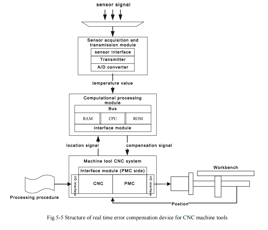
CNC machine tool error real-time compensation device structure diagram
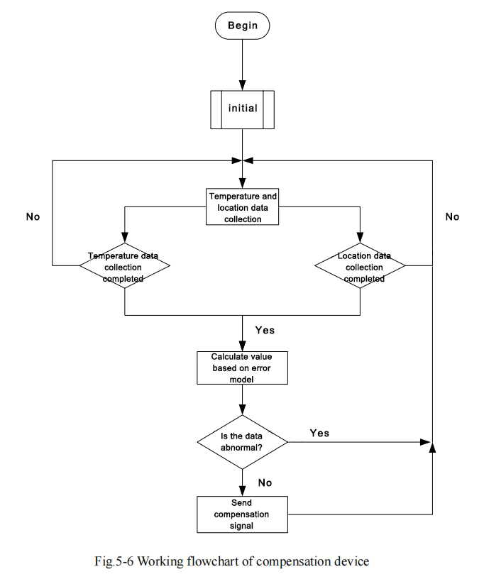
Workflow of CNC machine tool error real-time compensation device
The workflow of the real-time CNC machine tool error compensation device is shown in Fig. 5-6. When the compensation device is started, the device is initialized firstly, and after everything is normal, the data acquisition instruction is issued to read the temperature values of different channels into the memory in order from the data address corresponding to the temperature sensors, and at the same time, a trigger signal for reading the positional parameters is sent to the PMC, and the positional parameters corresponding to the machine tool are read into the memory. When the data acquisition is completed, the error value at the current position of the current temperature condition is calculated according to the mathematical model of positioning error. In order to prevent the misoperation of the machine tool coordinate home position offset, which causes machining error, the error value should be judged firstly, and if it is too large, the offset operation will be canceled, and if it is large, it will be compensated by the predetermined upper limit value, and this predetermined upper limit value is generally the maximum error value of machine tool. This predetermined upper limit value is generally the maximum possible error value of the machine tool. After the error data is judged and adjusted to the correct compensation value, the program sends a trigger signal to the PMC again, requesting to read in the compensation parameters, which include the compensation axes, compensation value, and compensation direction (expressed as the positive or negative of the compensation value).
After the PMC receives these compensation signals, one compensation work is completed and the system re-enters the data acquisition process.
Compensation device work transmission flow chart
The workflow of the PMC ladder diagram during the compensation process (excluding the original ladder program flow) is shown in Figure 5-7. After the machine enters normal operation, the PMC works according to the original ladder program, that is, the newly added ladder program does not have any effect on the work of the original machine.
In the working process, PMC receives a trigger signal to enter the compensation workflow, if the trigger signal is a request to send the position parameters, then the PMC will be the CNC system position register position parameters output, the output signal includes the axis number and the position parameters, when the position signals of all axes are outputted, then continue to enter the original program of the PMC, if the trigger signal is a request to enter the compensation value, then the PMC will be the compensation value of the original program, and then the PMC will enter the compensation value of the original program. If it gets a trigger signal requesting the input of compensation value, the PMC reads the compensation signal sent by the compensation device, including the axis number and compensation value, into the CNC system, and the axis control servo unit carries out the offset operation of the axes.
Again, after the operation is completed, the PMC continues to run the original program. Obviously, the added ladder diagram of the compensation program does not have any effect on the original machine tool work, and only works when it gets triggered, which is the greatest advantage of the device of the present invention. This compensation affects neither the coordinate values in the CNC nor the workpiece program executed on the CNC controller, and thus the method can be said to be invisible to the operator.
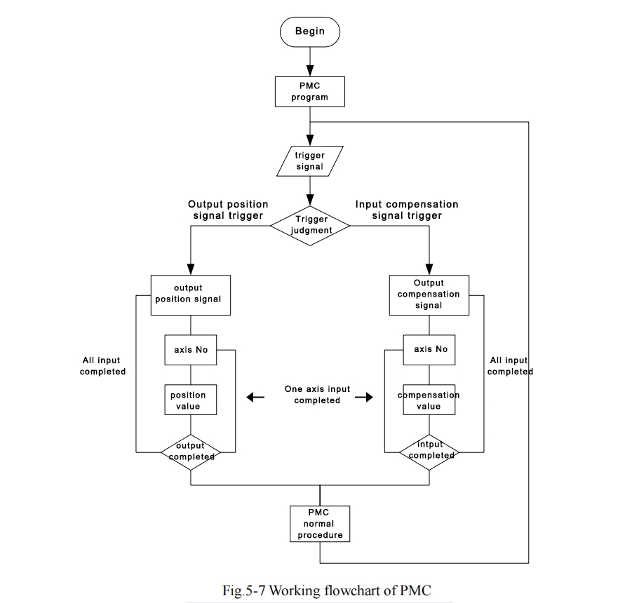
PMC work program flow chart