Hoods are generally used as seals, and need to be tested by gas, water and other pressure tests before assembly to ensure that the product will not leak to ensure that its assembly and use of the airtight, mostly for the whole casting or welded parts, with complex shapes, varied structures, different sizes, internal cavity, thin and uneven wall. In manufacturing, both the high precision requirements of the hole system, sealing grooves and planes, but also many shaped rounded corners, tabs and irregular surfaces, etc., processing and manufacturing difficulties [1].
1. part structure and process analysis
1.1. parts structure analysis
The cowling belongs to the box type parts, is a semi-enclosed polyhedron, cavity, inner wall is not uniform, the structure is mostly irregular, mainly used to ensure that the body within the body of the neat, reduce the noise generated by the body in the process of work, and at the same time can play a role in beautifying the appearance of the role. In machining, the processing elements are many, the processing volume is large, and the structure is irregular, resulting in a complex process [2].
1.2. process analysis
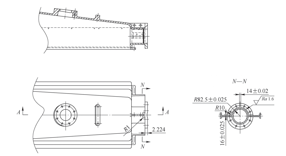
Hood: the blank is a whole cast iron part, the surface quality requirements are strict, the material is not easy to process, the tool wears fast, the space surface processing is difficult. Cover shell parts shown in Figure 1, in the flange on the back of the left and right sides of the arc, the middle is separated by 14mm ribbed plate, left and right is a symmetrical structure, the top and bottom of the single side to leave the side, the surface roughness value Ra = 1.6μm.
1.3 Difficulty analysis
The cover belongs to the box type parts, the material QT400-15 is ductile cast iron, high strength, good toughness, wear-resistant, vibration-absorbing and oxidation-resistant characteristics, but the cutting performance is poor. According to the requirements of the drawing, the back of the connection flange needs to be fully processed. One of the arc symmetrical distribution of left and right, separated by the middle of the bar plate, the processing of the arc surface as a whole perpendicular to the tool axis, the processing of surfaces need to fit the tool geometry to the surface of the knife path, in order to ensure that the final surface of the profile in line with the requirements of the process. As shown in Figure 1, the thickness of the fascia plate is (16±0.025)mm, (14±0.02)mm, and the root fillet R (82.5±0.025)mm, with high machining accuracy and strict surface quality requirements. Since the back of the flange is separated by the fascia, the use of three-sided edge milling cutter or lathe will interfere and can not be processed [3].

2. process and CNC machining methods
2.1 Machining method
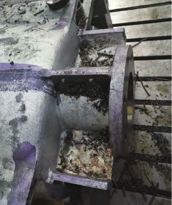
The arc surface of the part is a rotary surface, but its shape and structure for the box type parts (see Figure 2), so it is not suitable for the selection of turning class machine tools. The back of the flange is separated by 3 ribbed plates, the root of the rounded transition, the back, front dimensional accuracy and surface roughness requirements are high, can be selected in the three-axis and multi-axis milling machine processing. In multi-axis machining, since the mutual position of the tool and the workpiece changes at any time during machining, it is possible to complete all the machining in one clamping and obtain the optimal machining conditions. However, the procurement cost and software cost are much higher than that of 3-axis, the maintenance and repair cost is too high, and the operation skill requirement for operators is also higher, resulting in high labor cost. In the three-axis machine tool, the tool axis vector is unchanged, and the machining is done in the normal plane of the Z-axis, and the spatial surface machining can be accomplished by using linkage fitting, and better system rigidity can be obtained. Since this product is a large piece, small batch production mode, so there is no need to customize the tooling, the use of existing general-purpose isometric pads and downward pressure plate for positioning and clamping, can meet the production needs of this product. After on-site measurement of the machine tool milling head, analyzing the elements of the hood processing, can choose the ball end milling cutter in the ZY plane, along the Z-axis direction in the space lifting out the surface of the rounded corners, in order to obtain a better surface machining accuracy, quality and efficiency, as well as the best cost-effective.
2.2 tooling program
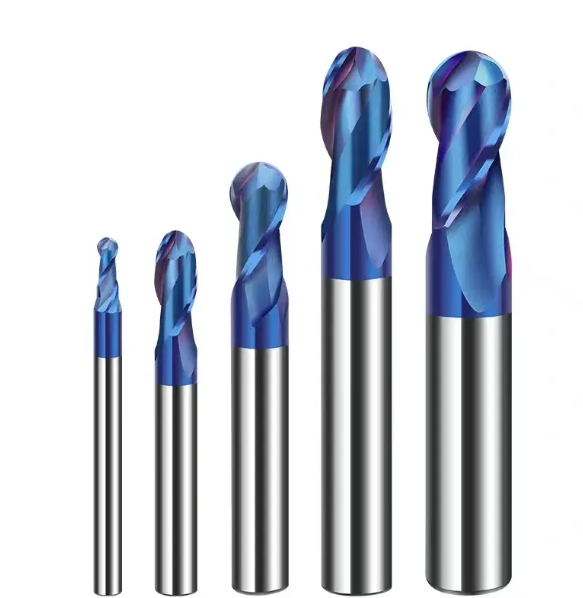
Tool selection and cutting dosage determination is an important part of the CNC machining process, not only affects the machining efficiency of CNC machine tools, but also directly affects the quality of machining, while making the entire machining cost changes. Combined with the characteristics of the machine tool, the performance of the workpiece material, clamping and process requirements, selected three-face edge milling cutter, end milling cutter and ball end milling cutter for machining. Since the three sections of the fascia plate on the back of the flange are evenly spaced at 90°, more residue is left at the root of the fascia plate by using a three-face flute milling cutter, and the side edges of the end milling cutter can be utilized to process all of them along the circular arc direction. The root arc surface is a three-dimensional surface, formed from the bottom up, and should be milled using a ball-end tool with a radius less than or equal to the minimum radius of curvature of the surface for interpolation. After measuring the blank 6mm allowance on one side is large, in order to ensure the processing rigidity and efficiency, choose the specifications shown in Figure 3 for φ20mm × 80mm × 150mm × 4F (YT) end milling cutter and R10mm × 80mm × 150mm (YT) ball end milling cutter.

2.3 Cutting program
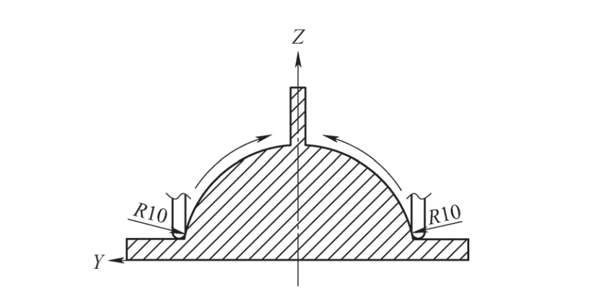
In the cutting process, according to the actual machining of the workpiece, in order to ensure the accuracy and surface roughness of the machining of the rounded curved surface, milling from the bottom upward using a clockwise milling sequential milling. Separate the tool starting point and tool set point. Under the premise of ensuring safety, the tool starting point should be as close as possible to the workpiece to reduce idle tool travel, shorten the feed path, and save execution time during machining. Because of the blank allowance is large, so the cycle of processing methods should be used in accordance with Figure 4 sequential milling, in the YZ direction to gradually remove the allowance, to the finish machining of 0.2mm allowance, during the period of attention to feed and exit point should be perpendicular to the direction of the Z-axis, the feed rate can not be “G0”, “G0” command should avoid “G0”, “G0”, “G0”, “G0”, “G0”, “G0”, “G0”, “G0”, “G0”. G0″ command should avoid “Y, Z” moving at the same time.
Tool cutting parameters selected: φ20mm end mill, tool material support line speed vc for 90 ~ 120m/min, back eating amount ap for 0.3 ~ 2mm, feed fz for 0.07 ~ 0.3mm/z.
R10mm×80mm×150mm (YT) ball end milling cutter, tool material support linear speed vc is 120~150m/min, back eating amount ap is 0.3~0.8mm, feed fz is 0.11~0.18mm/z.
Because the blank is a whole casting, affected by the casting process, the blank skin occasionally has hard spots, pores and sand entrapment. In order to reduce the quality risk and ensure the cutting stability, after the test piece debugging verification, the cutting parameters of φ20mm end milling cutter are vc=92m/min, n=1465r/min, ap=1.5mm, fz=0.07mm/z, vf=410mm/min; the cutting parameters of R10mm ball milling cutter are vc=130m/min, n=2070r/min, fz=0.07mm/z, vf=410mm/min; the cutting parameters of R10mm ball milling cutter are vc=130m/min, n=130m/min, n=2070r/min, vf=410mm/min. 2070r/min, ap = 0.5mm, vf = 228mm/min. After a batch of 12 pieces of machining, the use of the above cutting parameters, machining quality and stability, tool durability.

2.4 Programming
According to the geometric dimensions of the part drawing, calculate the running track data of the tool center. Since the circular surface is in the YZ plane, when machining with a ball end milling cutter, it is necessary to calculate the coordinate value of the contact point and complete the R82.5mm circular milling by point approximation. The final
purpose is to obtain all the relevant positional coordinate data needed for programming. The Y and Z coordinate values are calculated by trigonometric functions according to Figure 5: Y = Rcosα and Z = Rsinα.

In preparing the Heidenhain CNC program, Q1 = 17 is set as the starting angle, Q2 = 0.1 as the angle increment, Q3 = +76.5 as the ending angle, Q4 = 92.5 (R = 82.5 + 10) as the radius of the arc, and Q1 = Q1 + Q2 as the angle increment variable. After the program preparation is completed, before it is formally used for production and processing, the program running check must be carried out. In special cases, it is also necessary to do parts trial machining check. According to the results of the check, the program to modify and adjust, check and modify and then check and modify, which is often repeated many times until the program to fully meet the processing requirements.
56toolcall “d20-qtd “zs500
57lz+100r0fmax
58lx-50y-150r0fmax
59lz+26r0fmax
60LX+32R0F1000
61LY-88.771
62FN0:Q1=+17; //Starting Angle
63FN0:Q2=+0.1; //Angle increment
64FN0:Q3 = +76.5; //Final angle
65FN0:Q4 = +92.5; //Arc radius
66FN0:Q5 = +0
67FN0:Q6 = +0
68LBL2
69Q1 = Q1+Q2; //Angle increase variable
70Q5 = Q4×COSQ1; //loop to calculate Y value
71Q6 = Q4 x SINQ1; //loop to calculate Z value
72LY-Q5Z+Q6R0F1000
73FN12:IF+Q1LT+Q3GOTOLBL2; //loop judgment
74LY-21Z+90.085
75LZ+100FMAX; //Retract tool
76M0

3. Debugging processing and inspection
3, debugging processing and inspection
The machining origin of the surface fillet in the program is the center of the flange, i.e., X0, Y0 and Z0 in G54 are on the upper surface of the flange. Use the edge finder to centering in X direction and Y direction, then input the mechanical coordinates into the corresponding G54. After the Z direction with the centering bar or datum tool and the flange outer circle, calculate the Z value and input it into the G54. Let the machine run empty before machining to check the correctness of the tool trajectory. During commissioning, the spindle speed and feed multiplier in machining can be adjusted appropriately according to the actual situation (see Figure 6 for machining process) to achieve the best cutting performance. After the completion of the first piece is sent to the CMM to measure the linear dimensions, geometric tolerances and surface roughness, and the test results meet the process requirements.
4. Conclusion
Through the special use of ball end milling cutter, after many attempts to test, finally determined the machining of the cowling surface of the technology program, successfully solved the cowling space arc surface difficult to process, processing elements, processing precision and surface roughness requirements of strict and other difficult problems. It ensures the correctness of the hood machining, improves the controllability and stability of the machining quality, and finally forms the batch production capacity. At the same time, the method has a wide range of practicality and can provide help and reference for similar surface machining applications.
References:
[1] Yang Shuzi. Machining Technician’s Handbook [M]. Beijing: Machinery Industry Press, 2001.
[2] Lu Xiaoqin, et al. Programming technology of CNC machine tools [M]. Beijing: Machinery Industry Press, 2002.
[3] Zhang Shijun. Mold manufacturing in the CNC milling processing tool technology [J]. Metal Processing (Cold Processing), 2022(9):69-77.
