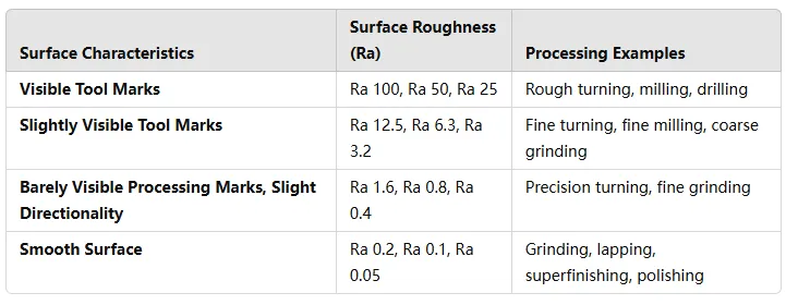
Parts in the machining of the machined surface of the microscopic unevenness, also known as roughness, to RaRzRy three codes plus figures to indicate that the mechanical drawings will have the corresponding surface quality requirements, generally is the surface roughness of the workpiece surface Ra <0.8um surface when called: mirror surface. Its processed surface quality directly affects the processed parts’ physical, chemical, and mechanical properties.
The working performance, reliability, and life span of a product depend largely on the surface quality of the main parts. Generally speaking, the surface quality requirements of critical parts are higher than those of ordinary parts. This is because parts with good surface quality will largely improve their wear resistance, corrosion resistance, and resistance to fatigue breakage.
Mirror surface – is the ideal state of metal cutting processing, and is the most effective means to improve the service life of mechanical components.
Mirror – is the traditional synonym for a metal surface that gets an excellent roughness after mechanical cutting and processing, which reflects the image of the item.
No matter what kind of metal machining method is processed, the surface of the part will always leave fine convex and concave cutter marks, staggered peaks and valleys phenomenon, roughing the surface with the naked eye can be seen, finishing the surface with a magnifying glass or microscope can still be observed. This is the part’s surface roughness after machining, which used to be called surface finish. National regulations surface roughness parameters by height, spacing, and comprehensive parameters.
The machining methods for obtaining a mirror surface are: the material removal method, and the non-cutting method (tumbling process).
Removal of material processing methods are: grinding, lapping, polishing, and EDM.
Cutting-free processing methods include: rolling (using mirror tools) and extrusion.
Parts drawings in addition to graphics, and dimensions, must be manufactured parts should meet some of the quality requirements, generally referred to as technical requirements. Technical requirements are usually: surface roughness, dimensional tolerances, shape and positional tolerances, materials and their heat treatment, surface treatment, and so on. The following first introduces the surface roughness and its method of injection.

Comparison of Processing Methods
Second, the concept of surface roughness
In mechanics, roughness refers to the microgeometric properties of smaller pitches, peaks, and valleys on a machined surface. It is one of the problems in the study of interchangeability. Surface roughness is generally formed by the machining method and other factors, such as friction between the tool and the part surface during machining, plastic deformation of the surface layer metal during chip separation, and high-frequency vibration in the processing system.
Due to the different processing methods and workpiece materials, the machined surface leaves traces of the depth, sparseness, shape, and texture are different. Surface roughness and mechanical parts with the nature of the fit, wear resistance, fatigue strength, contact stiffness, vibration and noise, etc. have a close relationship, the service life of mechanical products and reliability have an important impact.
The surface of a part is machined to look smooth but is uneven when viewed under magnification. Surface roughness refers to the surface of the machined part having a smaller pitch and tiny peaks and valleys composed of micro-geometric features, generally formed by the processing methods adopted or other factors.
The surface of a part has different functions and requires different values of surface roughness parameters. Surface roughness symbols should be labeled on the part drawing to indicate the surface characteristics that must be achieved when the surface is finished.
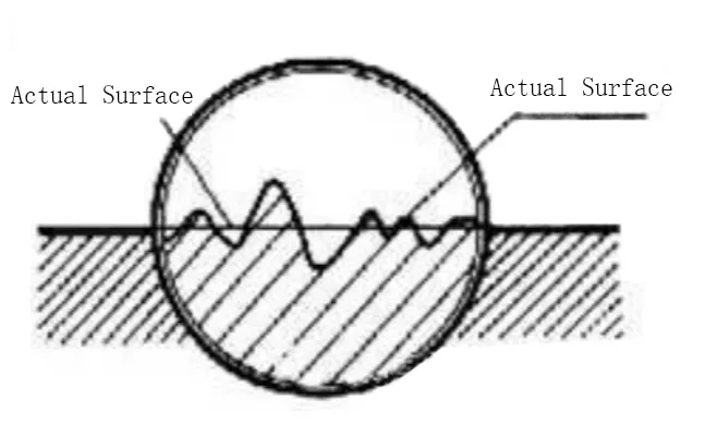
Regardless of which processing method obtained by the surface of the parts, are not flat and smooth, placed under a microscope (or magnifying glass) to observe, shall not be able to see microscopic peaks and valleys of uneven traces, as shown in Figure 1.
This microscopic unevenness on the surface is generally caused by various factors such as motion and friction between the tool and the part, vibration of the machine tool, and plastic deformation of the part. The surface has a small pitch and peaks and valleys composed of micro-geometric features, known as surface roughness.

Fig. 1 Concept of surface roughness
Surface roughness is to assess the surface quality of the parts of a technical indicator, it is on the parts of the nature of the fit, wear resistance, corrosion resistance, contact stiffness, fatigue strength, sealing properties, and appearance, etc. shall not have an impact. Therefore, the drawing should be based on the functional requirements of the parts, and the surface roughness of the parts to make the corresponding provisions.
The main parameter for assessing the surface roughness is the arithmetic mean profile deviation Ra, which is the arithmetic mean value of the distance yi from each point to the reference line on the supplementary profile line within the range of sampling length L. The arithmetic mean profile deviation can be measured by a motorized profilometer, and the arithmetic process is completed automatically by the instrument.
According to GB/T1031-1995F (in addition to GB/T3525-2000 at the same time to consult), the Ra value is smaller, the more the surface of the part is; the Ra value, the rougher the surface of the part.
There are 3 surface roughness height parameters:
Contour arithmetic mean deviation Ra
The arithmetic mean of the absolute value of the distance between the points on the contour line along the measurement direction (Y-direction) and the reference line within the sampling length.
- Micro-unevenness ten-point height Rz
means the sum of the average of the five maximum contour peak heights and the average of the five maximum contour valley depths over the sampling length.
- Maximum contour height Ry
The distance between the highest peak-to-peak line and the lowest trough-to-bottom line of a contour within the sampling length.
Ra is mainly used in the general mechanical manufacturing industry. Ra value is calculated by the following formula: Ra=1/l ∫t0|Y(x)|dx or approximated as Ra= 1/n ∑|Yi|. Where Y is the distance between the point on the contour line and the datum line (center line); ι is the sampling length.
Roughness is mostly used to characterize steel plates because they must have a certain degree of roughness before they are coated, otherwise the paint will not have enough bite and will come off easily.
III: Causes of formation
The main reasons for the formation of surface roughness are:
- Knife marks during machining;
- Plastic deformation during cutting separation
- Friction between the tool and the machined surface;
- High-frequency vibration of process systems
IV. Key performance
Surface roughness is mainly manifested in the following aspects:
- Surface roughness affects the wear resistance of parts. The rougher the surface, the smaller the effective contact area between the mating surfaces, the greater the pressure, the faster the wear.
- Surface roughness affects the stability of the nature of the fit. For clearance fit, the rougher the surface, the more prone to wear, so the gap gradually increased in the working process; for the surplus fit, due to the assembly of the microscopic peaks will be squeezed flat, reducing the actual effective interference, reducing the strength of the joint.
- Surface roughness affects the fatigue strength of the part. Rough parts have large valleys on the surface, and they are sensitive to stress concentrations like sharp notches and cracks, thus affecting the fatigue strength of the part.
- Surface roughness affects the corrosion resistance of parts. Rough surface, easy-to-make corrosive gases or liquids through the surface of the microscopic valleys penetrate the inner layer of the metal, resulting in surface corrosion.
- Surface roughness affects the sealing of the part. Rough surfaces do not fit tightly to each other, and gases or liquids leak through gaps between contact surfaces.
- Surface roughness affects the contact stiffness of the part. Contact stiffness is the combination surface of parts in the external force, the ability to resist contact deformation. The stiffness of the machine depends largely on the contact stiffness between the parts.
- Influence the measurement accuracy of the part. The surface roughness of both the measured surface of the part and the measuring surface of the measuring tool will directly affect the accuracy of the measurement, especially in precision measurement.
In addition, surface roughness can have varying degrees of influence on the plating and coating of parts, thermal conductivity and contact resistance, reflective and radiative properties, resistance to the flow of liquids and gases, and the flow of electric current on the surface of conductors.
