The key indicator for evaluating the performance of CNC machine tools is machining accuracy. CNC machine tools can guarantee machining accuracy within a certain range, but long-term and frequent use of CNC machine tools will cause them to be unable to maintain their original high accuracy. Therefore, it is very important to improve the machining accuracy of machine tools. Machining accuracy mainly depends on various machining errors, including inherent geometric errors of machine tool motion, assembly errors, and vibration errors. Among these error sources, geometric errors have the greatest impact [1].
Precision optimization design and error compensation are common methods to improve machine tool processing accuracy. Precision optimization design is a method of distributing geometric errors to key areas of the machine tool to improve machining accuracy. However, the impact of each geometric error on machining accuracy is different. If the geometric errors are distributed according to design experience, the optimization results may be distorted. , so reasonable allocation of the weight of each geometric error is a prerequisite for optimizing design accuracy.
Error compensation optimizes machining accuracy by compensating key geometric errors [2]. It uses the compensation characteristics of CNC machine tools to compensate for existing axis errors so that lathes with lower precision can produce higher-precision products through error compensation, which is a good example of CNC machine tools. The accuracy is guaranteed.
Using the error compensation method, production design should be carried out for different types of processing and error handling operations, and hardware solutions, software protection measures, and preprocessing measures should be adopted for their defects to reduce the risk of errors in the actual production environment.
To effectively improve the processing quality of parts and the production efficiency of CNC machine tools, it is necessary to improve the process conditions of CNC machine tool production equipment, improve process control capabilities, and increase processing accuracy.
1. Establish a machine tool error model
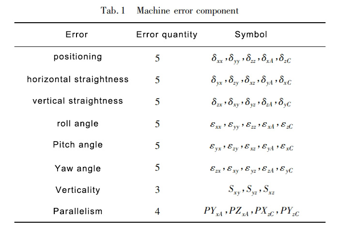
Modeling CNC machine tool errors Table 1 lists 37 error sources of CNC machine tools. Use a geometric error measuring instrument to measure the verticality and parallelism error axes. Other geometric errors are directly measured with a dual-frequency laser interferometer, linear error, and angular error. Represented by δ and ε respectively. For example, δᵧₓ is the linear error in the y direction along the x-axis. The first subscript is the direction of the error, and the second subscript is the direction of motion, which is the line axis.
mₑ$ₑ=[εₓ,εᵧ,εz,δₓ,δᵧ,δz]T (1)
Taking the x-axis component as an example, the first group includes linear positioning error δₓₓ and roll angle error εₓₓ, and the corresponding screw is $ₓₓ. The second group consists of horizontal straightness error δᵧₓ and pitch angle error εᵧₓ, and the corresponding screw is $ᵧₓ. The third group consists of vertical straightness error δzₓ and yaw angle error εzₓ, and the corresponding screw is $zₓ.
2. The impact of various geometric errors on machining accuracy
The “S”-shaped specimen has characteristics such as twist angle, opening and closing angle conversion, and variable curvature. It is widely used in the characterization of complex curved surfaces. Its contour error can truly represent the machining accuracy of the machine tool, so the “S”-shaped specimen is selected as the processing workpiece. In order to qualitatively analyze the impact of various geometric errors on machine tool machining accuracy, MATLAB is used for simulation analysis. The steps to achieve machining accuracy prediction are as follows: Use UGNX10.0 software to establish a three-dimensional model of the “S” shaped specimen, and obtain the tool position through the UGNXCAM processing module File, based on the tool positioning file, use the post-processor of UGNX10.0 to obtain the CNC machining instructions for the “S” shaped sample. Calculate the geometric error value at any position based on the establishment of a geometric error model. The machining error model and CNC machining instructions are used to predict the contour error of the “S” shaped specimen.
The key parameters of the machine tool are shown in Table 2. From the influence of various geometric errors on the machining accuracy of machine tools, it is found that different geometric errors and processing positions have different effects on the machining accuracy.

3. Geometric error compensation based on Floyd algorithm
There are two main methods for error compensation in CNC machine tools: manually adjusting the CNC machining program based on the error measurement during the machining process, and performing CNC error compensation by setting parameters and inputting prediction items in advance [4]. In recent years, the CNC tool path planning correction compensation method has become a widely used method to plan and solve the optimal tool path. Tool path planning methods include parallel shortest path search algorithm, ant colony algorithm, matrix-based load balancing incentive algorithm, enhanced bandwidth inversion shortest path algorithm, etc. The traditional compensation technique is to modify the error terms. The result is that each term depends on other terms. The reduction of some error terms may lead to the increase of other terms. Therefore, the compensation method of only modifying the key error terms is not acceptable or feasible. Floyd’s algorithm is a new path-planning method that is easy to understand and design.
Floyd’s algorithm is implemented by calculating the weight matrix [5]. The adjacency matrix D(0) represents the distance between two nodes, such as wᵢ, and wⱼ. Calculate D(1), find a possible path between wᵢ and wⱼ, compare and find the best path, and replace the original matrix with the new iterative adjacency matrix D(1). The elements in D(1) represent the optimal path between two points after one iteration. Adding 1 node between wᵢ and wⱼ will directly change the path to a better or shorter distance. In order to improve reliability, an iteration matrix D(k)=(d(k)ᵢⱼ) is established, a new node wr is set between wᵢ and wⱼ, and compared with the previous path length, if d(k-1)ᵣⱼ ≥d(k-1)ᵢⱼ, then the new path length will not be shorter than the previous node wᵣ. During the machine tool compensation process, the comprehensive error will cause the tool point position to deviate. This study determines the target wₜ, the compensation method aims to determine the shortest path, the actual point wⱼ, and the path length will be
another form of the wrong path length is
Since the actual point is not close to the target due to manufacturing defects, the compensation method function extends the actual target point to the target point. Once all possible paths between wᵢ and wⱼ are found, a better path is selected by comparison. Establish an iteration matrix D(k)=(d(k)ᵢⱼ), set a new node wr between wᵢ and wⱼ, and compare the path length, if d(k-1)ᵢᵣ≥d(k-1)ᵢⱼ Or d(k-1)ᵣⱼ≥d(k-1)ᵢⱼ, which means that the path length will not be longer than the previous node wᵣ. The measurement data are used to determine the parameters of the error model components along each axis, and the calculated Eₓ, Eᵧ, and Ez values are the values to be compensated.
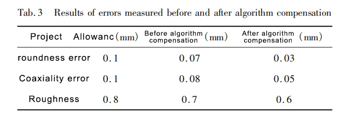
According to the mechanical industry standards, the roundness error and coaxiality error must be less than 0.1mm, and the roughness value must be less than 0.8mm. Comparing the machining accuracy of the workpiece optimized based on the Floyd compensation algorithm and the unoptimized workpiece, the results show that the optimized roundness measurement error is 0.03mm, which is smaller than the unoptimized roundness measurement value of 0.07mm. Before optimization, the same axis error is 0.05mm, and after optimization, the coaxial error is 0.08mm. Compared with the unoptimized workpiece, the surface accuracy of the optimized workpiece is higher, and the roughness value is reduced from 0.6mm to 0.4mm (as shown in Table 3). It shows that the Floyd compensation algorithm is effective in improving machining accuracy.
4. Conclusion
Model geometric errors of CNC machine tools and analyze the impact of various geometric errors of machine tools on machining accuracy. The results show that different geometric errors and processing positions have different effects on processing accuracy. Error compensation based on the Floyd algorithm was used to optimize the CNC machine tool-workpiece. A comparison of the workpiece processing accuracy before and after optimization found that the Floyd compensation algorithm was effective in improving the machine tool processing accuracy.