Restoring Precision: Practical Techniques for CNC Machine Alignment
Modern machining often utilizes milling and turning machining centers due to their high efficiency. However, their complex designs make them prone to collisions. These collisions can cause significant geometric accuracy deviations, even misaligning the main and sub-spindle concentricity. We have gathered our experience and developed practical techniques to simplify these adjustments greatly. Previously, they were time-consuming and labor-intensive, requiring professional engineers. Our methods ensure smoother production and minimize downtime.
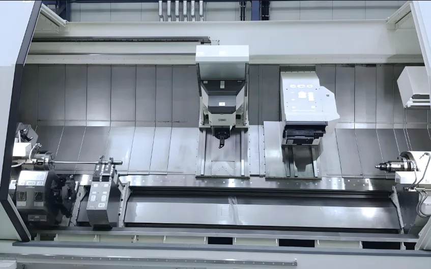
1. EMCO Milling and Turning Center: A Case Study
An operator error caused a collision in an EMCO HYPERTURN 65 milling and turning machining center. The machine had no mechanical damage. Still, key precision metrics, like the concentricity and parallelism of the main and sub-spindles, deviated by up to 1mm. We actively explored solutions and successfully restored the machine’s accuracy. This saved us from a long wait for the manufacturer’s engineers.
2. Precision Adjustment Method for EMCO Compound Machining Centers
For multi-axis adjustments, you must first establish a reference axis. Then, adjust the other axes sequentially. We chose the milling axis (Z-axis) as our reference. We then adjusted the machine in this order: main spindle, sub-spindle, milling axis, and finally, the turret.
2.1 Precision Detection and Adjustment of Main Spindle and Sub-Spindle
Accuracy inspections for both the main and sub-spindles cover radial runout, axial play, and end runout. First, clean the inner and outer surfaces of the spindle thoroughly.
To measure radial runout, attach a micrometer to the milling shaft. Press it against the spindle’s inner hole. Manually rotate the spindle.
To measure axial runout, use a calibration rod and a steel ball. Press the micrometer against the steel ball and rotate the spindle.
To measure end runout, directly measure the spindle end face with a micrometer. Then rotate the spindle (as Figure 2 illustrates).

2.2 Milling Axis Precision Adjustment
We primarily check the milling axis for its parallelism with the X-axis. We do this using an HSK63 mandrel and a micrometer. We observe any numerical deviation as the X-axis moves. If adjustment is necessary, loosen the fastening screws. Gently tap the milling axis with a wooden hammer to make small adjustments. Continue until it reaches the allowable error range. Finally, tighten the screws and re-measure.
2.3 Lower Turret Precision Adjustment
After a collision, the lower turret cutter disc on a HYPERTURN 65 had a center deviation of up to 1mm. This mainly happened due to clearance in the fixing screws. We loosened these screws. We carefully tapped with a wooden hammer and took repeated measurements. We successfully adjusted the turret’s center accuracy to within 0.015mm. This completed the precision calibration of all axes on the machining center.
3 JOBS Gantry Milling Machine: XY Axis Verticality Adjustment
A JOBS gantry milling machine, introduced in 2002, experienced a continuous buildup of X/Y axis verticality deviation from long-term use. Its X-axis dual motor linkage worsened this problem. By removing the X-axis linkage control, we significantly simplified and improved the efficiency of X/Y axis verticality adjustments. We also reduced associated risks.
3.1 Adjustment Method Before Improvement
Previously, adjusting the X/Y axis verticality on the JOBS gantry milling machine involved loosening the screws connecting the column and the beam. Then, we used the X-axis zero return to level the deviation. This method was time-consuming, labor-intensive, and risky.
3.2 Improved Adjustment Plan
Our improved plan begins by measuring the verticality of the X/Y axis. We then unlock the X1/X2 axes for separate control. We do this by modifying the parameter “37100 GANTRY AXIS TYPE.” Next, we fine-tune the X1/X2 axes based on the verticality deviation until we eliminate the deviation. Finally, we re-tighten the screws and restore the original parameters. This new solution carries less risk and offers greater efficiency.
3.3 Precision Adjustment Effect
After completing the X/Y axis verticality adjustment, we used a 400×400 square ruler to verify the X/Y verticality. We achieved 0.005 mm/400 mm. This result ensured the machine’s processing accuracy met user requirements. This adjustment also solved the problem of excessive load on the X1/X2 axis motors, which had caused significant X/Y axis verticality deviations.
4 Conclusion
Geometric accuracy adjustment of CNC equipment is crucial for maintaining processing accuracy. This is especially true for high-precision multi-axis imported equipment, such as turning and milling compound machining centers, and large equipment, like gantry milling machines. The adjustment process is complex and demanding. However, our experiences show that practical, improved techniques can significantly reduce the difficulty and time needed.