A plate bending machine is a specialized forging and pressing equipment.A simple mold pushes the metal sheet into the required geometric shape. This process is widely used in electrical appliances. It is also used in electronics, metal structures, instruments, meters, daily-use hardware, construction, and decoration.
A commonly used bending machine is the hydraulic transmission mode. The matching bending mold and general bending machine support supplies complete a variety of complex workpiece bending. They ensure high product quality and high productivity. These products are widely used. Bending machines and supporting molds can easily manufacture workpieces with different and complex shapes.
Automatic CNC bending machine has been put into use in the precision processing of steel bending workpieces with the continuous expansion of the field of application, the requirements of the plate bending machine are also higher and higher, to meet the ever-increasing technological requirements, a variety of new structure of the plate bending machine came into being, the local innovation and improvement is endless.
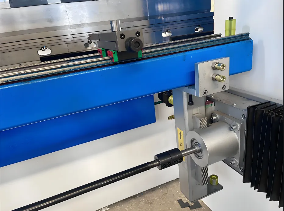
Market requirements for plate bending machines have changed. Initially, bending was manually controlled. Now, the process requires automatic and precise control of the plate bending rebound. As a result, the development of bending machines must adapt to these new market demands.
The basic structure of the bending machine
Currently, the market divides power source bending machines into two categories: hydraulic bending machines and electric bending machines. Hydraulic bending machine development earlier is still the mainstream product on the market. With the rapid development of servo motor technology, electric servo bending machines have rapidly developed in recent years.
The structure of the hydraulic bending machine is shown in Figure 2. The hydraulic cylinder mainly applies downward pressure and feeding. It includes the main cylinder, the upper body, the convex mold, the concave mold, the base, the feed cylinder, and other parts. The upper body mounts the main cylinder. The output end of the main cylinder connects to the convex mold. When the main cylinder acts, it drives the convex mold downward. The convex and concave molds work together to bend and form the sheet. Meanwhile, the feed cylinder uses a screw to determine the sheet’s position, ensuring the sheet bends and forms in a fixed position.
Structure of electric bending machine
As shown in Figure 3.
The servo motor and screw mainly realize the downward pressure and feeding of the electric bending machine. The system includes the servo motor, upper body, screw, slide, convex die, concave die, base, feeding system, and other parts. The upper body installs the servo motor and connects it to the screw through a coupling. When the servo motor rotates, it drives the screw to rotate. This rotation moves the slider in a straight line and drives the convex die downward. The convex and concave dies work together to bend and form the sheet. The servo motor also drives the sheet feeding process.
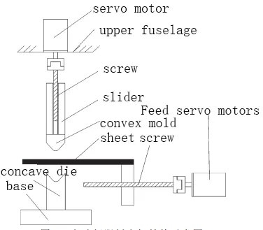
Fig. 3 Schematic structure of electric servo bending machine
New bending machine development trend
As social productivity continues to develop, the product precision requirements in the plate bending field keep improving. New technology is being used more and more in bending machines. The following summarizes the main development direction of the plate bending machine.
High-power multi-axis synchronized servo bending machine
In recent years, the improvement of precision requirements for parts processing has led to the widespread development of electric servo bending machines. Enterprises can also produce lengths of more than 20m bending parts. Of course, for the length of the larger bending parts, the use of a single-axis bending machine makes it difficult to meet the requirements of the forming force, and therefore still more multi-axis synchronized bending machine.
For hydraulic bending machine, solving the problem of synchronization of multiple hydraulic cylinders is more difficult, in practice, it is also easy to leak oil and fail. Electric bending machine through several servo motors to achieve the lower pressure of the slide, the synchronization of the control problem is simpler than the hydraulic cylinder, so the electric servo bending machine can achieve multi-axis synchronous work to achieve high-power bending.
Some scholars have proposed a four-axis synchronous high-power all-electric bending machine synchronization control method,In the no-load high-speed downstream stage of the bending machine slider, the system uses a deviation coupling synchronization strategy. This strategy is based on speed synchronization control. The main idea is to reduce the speed of one motor according to the speed feedback of the other motor. The system then adds the deviation to the motor’s given speed command to achieve motor synchronization.
In the pressurized bending stage, the low speed and the presence of load impedance force make the mechanical coupling between the axes more effective. This allows the system to achieve motor synchronization. The compensation for the moment of inertia also helps achieve motor synchronization.
During the pressurized bending stage, the low speed and load impedance force reduce the mechanical coupling between the slider axes. Four motors adaptively adjust their output torque based on the load pressure until the pressure holding is complete. At the clamping point, the system switches from synchronized drive control to an independent position loop P control. This ensures the accuracy of the bending angle control.
There are scholars will be open CNC system and servo bending machine combination, proposed a mutual master from the three-axis synchronization control strategy, as shown in Figure 4. The control signals are compared with the feedback signals of the three axes. Then, the system compares the results of the two adjacent axes (Y1 and Y2, Y2 and Y3). The comparison results are sent to the control module. The control module generates an adjustment signal and sends it to the controller. This process achieves mutual master-slave synchronous control of the Y1, Y2, and Y3 axes.
Servo bending machine with the application of a new type of reduction mechanism
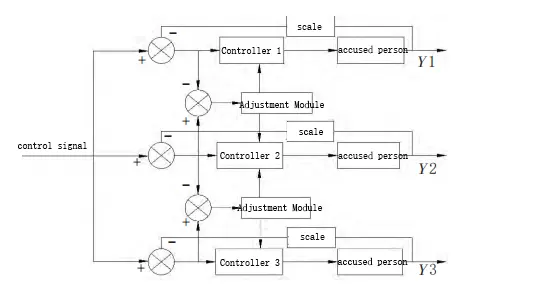
Fig. 4 Mutual master-slave synchronization control principle
As electric servo bending machines rapidly develop, manufacturers now use many new types of reduction mechanisms in them. Since the motor is suitable for working at higher speeds, the electric servo bending machine needs to adopt a reduction mechanism to improve the output force of the bending machine. Many scholars have combined the new type of reduction mechanism with the bending machine to propose a new type of bending machine with a simple structure, high efficiency, and good control performance.
Some scholars will be cycloid gear reducer and servo bending machine, designed a new type of bending machine, cycloid gear reducer can achieve very high reduction ratio, in the bending machine has a very good prospect of application. It can achieve more than 90% efficiency, and at the same time, the combination of the
The structure is compact and small in size. It can integrate with the upper body of the bending machine. The application of a cycloid gear reducer in an electric bending machine is conducive to reducing the bending machine’s demand for motor capacity, at the same time, cycloid reliable operation, the advantage of long life can reduce the number of bending machine maintenance, improve production efficiency. Its main structure is shown in Figs. 5 and 6.
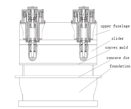
Fig. 5 Cycloid servo bending machine
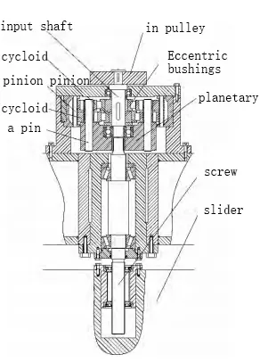
Figure 6 Schematic diagram of the structure of the cycloid reduction mechanism
Another scholar has designed a new type of harmonic reduction bending machine by integrating the harmonic reducer and motor in the aerospace field and then applying it to a servo bending machine. A harmonic reducer is a new type of mechanical transmission developed for the aerospace field. Its main structure includes a rigid wheel, a flexible wheel, and a wave generator. The wave generator has an elliptical cross-section structure. The flexible wheel is a thin-walled, simple external gear. The rigid wheel is an internal gear ring with high rigidity.
When the harmonic speed reducer works, the motor drives the wave generator to rotate, so that the flexible wheel can control elastic deformation because the wave generator is elliptical, so it will make the flexible wheel rotate the elliptical elastic deformation of the long axis, which will make the flexible wheel in the wheel to occur the wrong tooth movement, the axis of the flexible wheel to rotate slowly, to realize the deceleration.
The harmonic deceleration bending machine is suitable for use in high precision small electric servo bending machines and can realize the accurate control of the bending process of the sheet, such as Figure 7, Figure 8 is the use of harmonic drive servo bending machine power system schematic diagram.
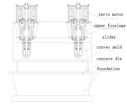
Fig. 7 Servo bending machine with harmonic reduction mechanism
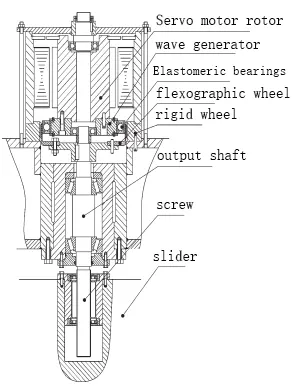
Fig. 8 Schematic structure of harmonic reduction mechanism
Online correction of bending spring back by applying machine vision
In recent years, machine vision technology has rapidly developed and found applications in many fields. Vision inspection technology uses a machine (camera) to replace a person for measurement and judgment tasks. The image acquisition device captures the measured objects and converts them into image signals, instantly collecting large amounts of information. The image processing system processes this information. It calculates characteristics such as size, shape, and color based on the distribution of pixels, height, and color.
Machine vision is particularly suitable for applications where manual measurement and hazardous working environments are not suitable. In sheet bending, manual measurement is difficult to carry out, and at the same time, the measurement error is large, which makes the machine vision has a wide range of application prospects. Bending machines with machine vision for bending angle monitoring can realize online quality monitoring and correction of bending angle.
Some scholars have proposed using binocular vision for full-length detection during the sheet bending process. The binocular camera instantly acquires tens of thousands of data points. The system then processes the point cloud data using an improved surface growth method, an enhanced eigenvalue method, and a coordinate transformation alignment method. These methods yield high-precision measured angle values. The processing steps are shown in Fig. 9.
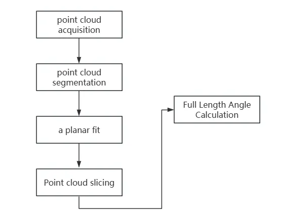
Fig. 9 Workflow of binocular vision full-length bending angle measurement
Adopting the binocular vision measurement method, it can quickly complete the accurate measurement of the angle of the bending parts, and realize the online detection and correction of the bending angle of the bending machine. This detection method is simple, safe, rapid, and accurate, the single run time is only about 0.5s, and the measurement error is less than 0.5%, to meet the requirements of plate bending accuracy.
reach a verdict
(1) In recent years, China’s plate bending production capacity of enterprises continued to improve, and the demand for high-power bending machines increased, electric servo bending machines can make it easier to achieve multi-axis synchronous work, to obtain a larger bending power, and thus have a broad market application prospects. In the high-power multi-axis synchronous servo bending machine, the system can use the same servo motor as the master for each axis in synchronous control mode. This setup ensures the motors work in synchronization. As a result, the machine can generate a larger bending force.
(2) in the electric servo bending machine, applying a new type of deceleration mechanism to enhance the bending force of the bending machine, so that the equipment structure is compact, improves efficiency. Cycloid reduction bending machines have reliable operation, and long life, in some of the requirements of the maintenance of a small number of occasions have a huge advantage; harmonic reduction bending machines with high precision: able to produce high-precision bending parts, to achieve high-quality plate bending parts of the independent production of domestic.
(3) Machine vision replaces manual measurement in the bending machine. Binocular vision measures the full length of the bending parts. It quickly and accurately captures the bending angle. The system provides online feedback and corrects spring back.The production of high-precision plate bending parts no longer needs to accumulate many experiments through the equipment process database, but through the full closed-loop approach to improve the bending accuracy of the bending machine. This full closed-loop bending machine than the same precision servo bending machine price is low in the high-precision bending machine market and is very competitive.
