Since 2002, China has become the world’s largest consumer of machine tools and machine tool imports of the largest country with a serious import and export deficit in high-grade, large, precision, high-speed CNC machine tools, and CNC systems import dependence is more obvious. 2005 high-grade and large-scale CNC machine tools imports reached 5.2 billion U.S. dollars in 2006, and it has increased to 6.4 billion U.S. dollars. At present, China’s imports of high-grade, large-scale, precision, and high-speed CNC machine tools, and more than 70% of China’s automobile manufacturing equipment and more than 90% of automobile engine production lines are dependent on imports.
What Is Five-Axis Linkage CNC Machining
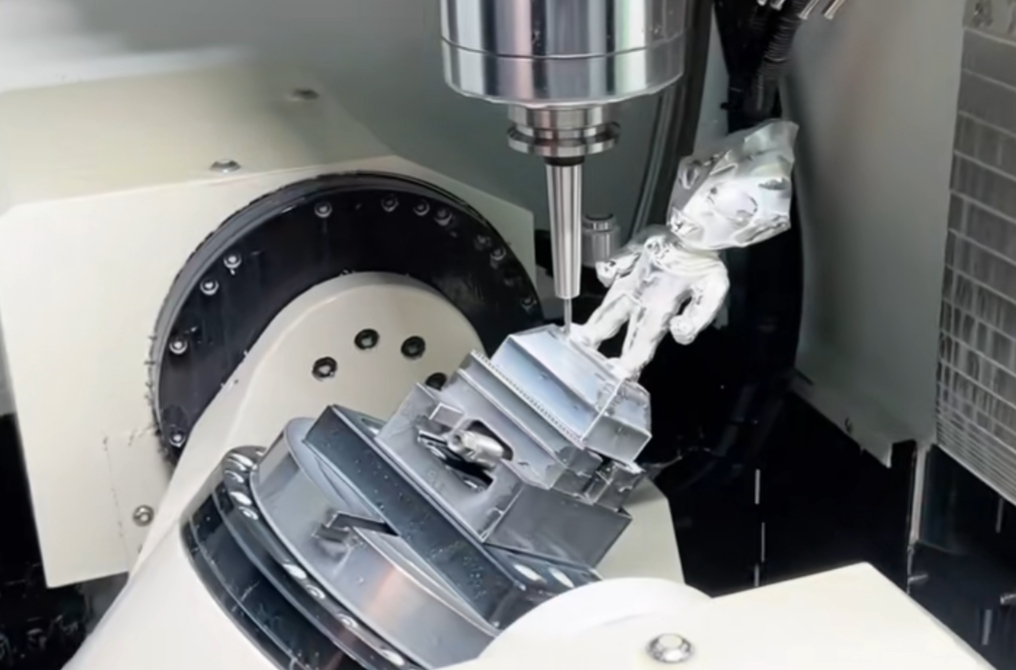
Five-axis linkage machining center has high efficiency and high precision, the work of clamping can be completed by five-sided machining. Such as the configuration of the five-axis linkage of high-grade CNC systems can also be a complex space surface for high-precision machining, more suitable for more and more complex high-grade, advanced mold processing and automotive parts, aircraft structural parts and other precision, complex parts processing.
As we all know, developed countries until now are still restricting the export of five-axis linkage CNC systems and machine tools to China, if the users use foreign CNC systems, they have to sign a strict directional use agreement and accept the inspection.
Structure of 5-Axis CNC Machining Center
A 5-axis CNC machining center is a sophisticated machine tool used in manufacturing and machining processes. It offers greater versatility and precision compared to traditional 3-axis machines because it can manipulate the workpiece in five different axes of motion. This allows for more complex and intricate machining operations.
Five-axis linkage machining centers are mostly 3 + 2 structures, that is, xyz three linear axes plus three rotary axes around the xyz axis rotation abc three rotary axes in the two rotary axis composition. This classification from the big aspects of xyzab; xyzac; xyzbc three forms; by the combination of two rotary axes to the form, roughly, there are double rotary table, rotary table plus the pendulum head type and double pendulum head type three forms. These three forms of structure due to physical reasons, respectively, determine the size of the machine specifications and the range of processing objects.
Among them, the double rotary table structure of the five-axis linkage machine tool is only suitable for machining small parts because the workpiece needs to move in two rotational directions when machining the workpiece. Such as small whole turbines, impellers, small precision molds, etc., due to the simplest structure, so the relative price is relatively low, in terms of application, this is the largest number of a class of five-axis linkage CNC machine tools.
Machining Modeling for 5-Axis Machine Tool Machining, Programming (Cad/Cam System)
Modeling and programming for 5-axis machine tool machining involve creating a digital representation of the part or component you want to machine and generating the toolpaths and G-code necessary to control the 5-axis CNC machine. This process typically requires the use of CAD (Computer-Aided Design) software for modeling and CAM (Computer-Aided Manufacturing) software for programming. Here’s a step-by-step overview of the process:
CAD Modeling
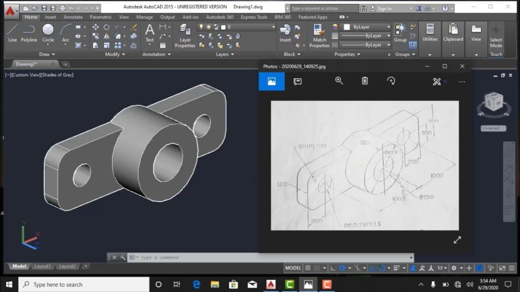
Design the Part: Begin by designing the part or component you want to machine using CAD software. This involves creating a 3D model of the part, specifying dimensions, and defining the features and geometry of the part.
Define the Workpiece: In the CAD software, specify the raw material’s dimensions and shape (block, cylinder, etc.) that will be used as the starting material for machining. This is essential for simulating the machining process accurately.
Establish the Coordinate System: Define the part’s origin and coordinate system. The coordinate system helps in accurately positioning the part within the 5-axis machine and is crucial for generating toolpaths.
CAM Programming
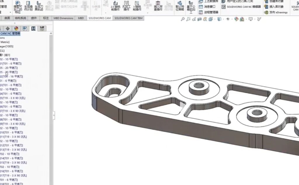
Import the CAD Model: Import the 3D CAD model of the part into your CAM software.
Set Machining Parameters: Define the material, cutting tools, and machining parameters such as feeds, speeds, and cutting depths. These settings ensure that the CAM software generates appropriate toolpaths based on the material and tools being used.
Select the Machining Strategy: Choose the appropriate machining strategy based on the part’s geometry and the desired surface finish. This can include strategies like contouring, parallel machining, and scallop machining.
Toolpath Generation: The CAM software generates toolpaths that guide the 5-axis machine’s cutting tool as it moves over the part’s surface. For 5-axis machining, this involves simultaneous movement in multiple axes, including tilting and rotating the tool and the workpiece to access complex features.
Collision Detection: CAM software typically includes collision detection features to ensure that the tool and machine components do not collide during machining. It adjusts toolpaths to avoid collisions.
Post-Processing: After generating the toolpaths, the CAM software generates the G-code that the CNC controller will understand. This G-code specifies the tool’s movements, speeds, and tool changes.
Simulation and Verification
Before sending the G-code to the 5-axis CNC machine, it’s crucial to simulate and verify the toolpaths. CAM software often includes simulation features that allow you to see how the tool will move and how the part will be machined. This helps identify potential issues and ensures that the toolpaths are correct.
Machine Setup
Set up the 5-axis CNC machine, secure the workpiece, and load the appropriate cutting tools into the tool magazine.
Quality Control
After machining is complete, perform quality control checks on the machined part to ensure it meets the design specifications.
The combination of CAD and CAM software, along with a 5-axis CNC machine, allows for the efficient and precise manufacturing of complex components. The modeling and programming process plays a critical role in achieving high-quality and accurate results.
5-Axis CNC System
A 5-axis CNC system is a computer numerical control (CNC) system that controls a 5-axis CNC machining center, which is a highly advanced machine used for machining complex parts and components with precision. The 5-axis CNC system includes hardware and software components that work together to control the movement of the machine’s cutting tool in five axes of motion. These five axes of motion are typically labeled X, Y, Z, A, and C, and they allow the tool to move in various directions, making it capable of intricate and complex machining operations.
Here’s an overview of the key components of a 5-axis CNC system:
CNC Controller
The heart of the system, the CNC controller is a computer that reads and processes the part program or G-code. It interprets the code and sends commands to the machine’s motors and actuators to move the tool accurately. The CNC controller also provides the operator with the interface to input program data and monitor the machining process.
Axis Motors and Drives
These are responsible for moving the various axes of the machine. In a 5-axis CNC system, there are typically three linear axes (X, Y, Z) and two rotary axes (A and C). Each axis has its motor and drive components to control movement.
Tool Changer
A tool changer is a mechanical system that automatically changes cutting tools as needed during machining. It selects the appropriate tool from a magazine and places it in the spindle, allowing for continuous and automated machining without manual tool changes.
Spindle
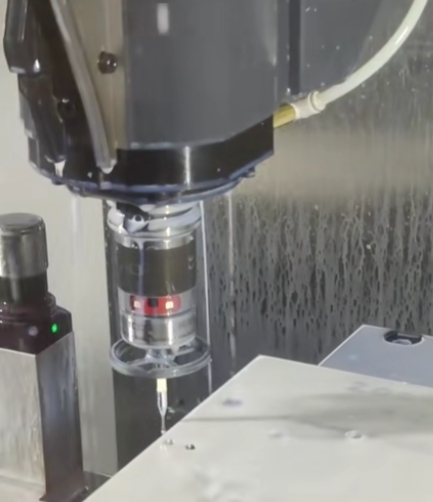
The spindle is the component that holds the cutting tool. In a 5-axis system, the spindle can rotate and tilt, which enables the tool to approach the workpiece from various angles.
Feedback Systems
To ensure precision and accuracy, feedback systems like encoders and sensors are used to provide real-time information on the position and movement of the machine’s components. This feedback is sent back to the CNC controller for closed-loop control.
Rotary Tables
Rotary tables are used for the A and C axes. The A-axis tilts the workpiece, while the C-axis rotates it. These tables can move in a continuous or incremental manner, allowing the tool to access multiple sides of the workpiece.
Coolant and Chip Management
Many 5-axis CNC systems have coolant systems to keep the cutting tool cool and remove chips and debris from the machining area. Proper coolant and chip management are crucial for maintaining the tool’s performance and workpiece quality.
Safety Features
Safety features, such as emergency stop buttons, interlocks, and safety guarding, are important to ensure the safety of operators and protect against accidents.
Programming and Software
CAD/CAM (Computer-Aided Design/Computer-Aided Manufacturing) software is used to create the part program or G-code that specifies the toolpaths and machining operations. This software generates the code that the CNC controller reads and executes.
5-axis CNC systems are highly versatile and are commonly used in industries such as aerospace, automotive, medical device manufacturing, and precision engineering, where complex and precisely machined parts are required. They offer the capability to produce intricate and challenging components with a high degree of accuracy and efficiency.
Conclusion
Five-axis linkage machine tools are harder to use than three-axis machine tools, and the cost, programming complexity, and operator’s requirements are also much higher, but why do people around the world are choosing the five-axis linkage machining?
The benefits of using five-axis linkage machine tool machining are, that you can do the so-called complex workpiece “one card, all done” five-sided machining effect, effectively solving the problem of error due to the secondary loading; secondly, you can do the tool’s constant linear speed cutting, so as to get a high cutting efficiency and precision, as well as uniformity of the machining roughness; Then is the five-axis linkage machine tool can be processed ordinary three-axis machine tool due to tool “interference” and can not process the workpiece, such as the whole impeller, some high-grade molds and so on. The above points can make the five-axis linkage machine tool be efficiently processed three-axis machine tools are not able to get high quality and high precision of complex parts.
With technological advances, five-axis linkage machine tool manufacturing and application technology is becoming more mature: advances in CNC systems, servo drive technology advances in “zero transmission” technology advances in rotary axis technology and promote the five-axis machining related to the rapid progress of CAD / CAM technology and the importance of the relevant training, etc., making the Five-axis linkage machine tool manufacturing and use of costs show a downward trend, and thus in the world five-axis linkage machine tool applications will become more and more widespread.